Showing posts with label muzzle velocity. Show all posts

Friday, 28 April 2017

.177 BSA Cadet, A Review and Other Bits and Bobs


For an old air rifle that i always thought a bit of a smallish youth rifle, i was pleasently surprised to find it both considerably larger and heftier when i first laid my hands on one. 

109 cm from tip too tail

The very first thing i did though was to put her over the chronoghraph to get 4.56 ft/lbs with JSB Exacts, she was old, complete and in fairly good nick and i reckoned things could only improve from here on in.

This has the look of a sporting rifle in the 50's

 BSA was responsible for the production of over 50% of all British small arms produced during WWII, so roll on 1945 and they decide to go back to an increase in thier Air rifle production and the introduction of thier new Cadet air rifle. Capable of putting out 8 ft/lb and advertised as being able to take rabbits out to 50 yards this rifle was popular amongst young adults and adults alike, trade description was not an issue in those days. Maybe if you could throw the thing 50 yards you could possibly concuss a rabbit, with a full wooden stock and heavily engineered steel construction the rifle had some interesting early BSA design features and had to be one of the prettier looking break barrel air rifles for it's time.

The prefix of CC tells me the rifle is made in the later half of the 1950's

The Cadet has a leather piston seal which in this case needed no oil to improve velocity, from what i remember from the chrony test there was no more the 25 FPS spread with any of the pellets i tested. From what i could see through the cocking slot both spring and piston appeared to be lightly lubricated, or at least it wasn't all dry and dusty. 

The Cadet has a one peice trigger and sear that hooks on to a central piston rod in the piston, how much of the sear that holds the piston rod can be adjusted by a screw in the slope at the rear of the action.

Without dimantling the rifle i had to looke at the plans on Chambers web site too find out this adjusted sear engagement.

 The stock is a one piece beechwood affair with a very long cocking slot, because it has a single piece cocking rod that is, like the rest of the rifle, very well made and solid.

Considering the length of the cocking slot, there was no movement in the stock, not one bit, non at all, zero, zilch.


The stock fits well to the action and is fixed with two screws at a 60 degree angle at the front of the action,

Screws made the old fashioned way, roled on the thighs of dusky Brummies.

and like the later Airsporter and Mercury the rear is a bolt that runs through the pistol grip and screws into the rear section of the action. 

The reat bolt. Like it say's on the tin, bolts the rear on.

The Cadet has some weight to it for its size as i said before and although it is pretty old there is no movement between the forks, or anywhere at all come to think of it, from wear over the years.


I have no idea if a pin or a bolt holds the forks around the breech, it's still a solid fit though.

There are only open sights on this rifle and has no scope rail, because scopes just weren't commonly used in the 50's. The front sight is a bead on top of a concave ramp that sits in a dovetail on the tip of the barrel, left to right adjustment could be achieved by tapping the sight along the dovetail.

The front sight had already been adjusted and was fine, notice it hangs over too the right.


From this angle the dove tail is more noticable.

The rear sights that sit on top of the breech block are real old school and tend to be found on most early 1900's air rifles, they adjust up and down only by spinning a firm horizontal thumb wheel. This allows a plate with a V notch on top to move vertically in its frame, score marks on the side of the frame and plate help keep track of adjustments


These sights were perfectly fine in the 50's and still perform well today.

The trigger and guard are very slim but also pretty solid due to the fine quality of the metal used to build it. The trigger appears to have a light too mediun release and along with the angle of the pistol grip and the low combe on the buttstock, found it very comfortable too shoot with satisfying results.

The trigger guard design is a tried and tested BSA design and can be found on later Meteors

Low recoil, trigger release, weight, and pretty nifty old school sights all added up to some good off hand accuracy. 7 out of 9 Geco wadcutters made one impressive one cm ragged hole and JSB Exacts appeared to spred vertically, however they were the only two pellets i tried at the time.

I reckon Superdomes would do well in this air rifle, should get some really.

When all is said and done, the BSA Cadet is an awesome back yard plinker that reeks of nostalgia from a time we can only imagine and most likely never happened.

This rifle came to me in good condition internally and out, and as a plinker did not need any attention apart from a little oil and wire wool for the matal work. It's fun and definately gets a thumbs up.

All the best,

Wing Commander Sir Nigel Tetlington-Smythe 

Thursday, 24 September 2015

.22 Mk I Sharp Innova, A Restoration Project. Restoring The Exhaust Valve, A Detailed Guide.


This blog entry is going to be in as much detail as I can manage, as I want it to be the sort of thing that I would have found really helpful the first time I worked on the Sharp Innova. I have already stripped and inspected this air rifle in a previous blog entry HERE , so today I will repair the exhaust valve using the T.R Robb Sharp Innova seal repair kit and test the power output.

The T.R Robb exhaust valve repair kit, which consists of a stainless firing pin, exhaust valve spring, a red inlet packing seal, an inlet ball seal, two big O rings for the valve guide seal and chamber seal, and two small O ring seals for the transfer port and inlet valve seal. Also a blob of silicone grease for the seals and a small bottle of silicone oil for the pump rod seal.

It is important to have a clear working space so you can keep track of all parts that have been removed, I keep small parts in a tin as it's a real bugger if they get lost. I am lucky in being able to do my work on the dining table, however the dog thinks that the table is also his bed.

The dog whines a lot if I move him from his bed.

So here is the guide in all it's tedious, mind numbing, gut wrenching detail.

Remove the action from the stock. Then remove the circlip from the pin that connects the pump arm to the front of the cylinder. Drift out the pin with a suitable sized punch. The pump arm can now be removed through the pump slot in the cylinder - it may need to be wiggled a bit.

Pin and circlip already tapped out.

Next, drift out the smaller roll pin in front that secures the sight unit to the cylinder; this can be a bit stiffer but it will move more easier using the correct sized pin punch. 

Correct sized pin punch for the roll pin is important.

Grasp the sight unit and pull it from the cylinder, outer barrel and inner barrel. This may need a lot of wiggling if it's not been removed for a long time.


Pull the pump rod down to the front of the cylinder using the pump arm linkage and line up the pivot pin with the hole for the pump arm linkage and cylinder. Twist the brass pump arm pivot base a little so the pivot pin lines up with a hole on one side; only half of the pivot pin will be visible in the hole on the other side so tap it out from this side with a smaller pin punch. 

Old dart head makes an excellent small pin punch.

Remove the pump arm linkage from the pump rod and remove the pump rod through the front of the cylinder, push it out with a screwdriver at first, then pull it out the rest of the way.

Pump rod shouldn't be this greasy.

To remove the cylinder from the breech block, first remove the brass collar screw on the underside of the breech ...

Only finger tight , the stock screw locks the collar screw in place.

... then using a flat head screwdriver, remove the stud screw under this.

This stud screw appears to hold the whole rifle together.

Remove the spacer that sits between the bottom of the cylinder and breech block; use a thin blade to lever it out at first, then it should slide out by hand.

A little tab on the spacer is good for leverage.

Remove the cylinder with the exhaust valve inside from the breech block, this should drop into the breech hole and pull out easily, revealing the transfer port O ring on top of the cylinder.

Transfer port O ring seal is pretty swollen.

Unscrew the exhaust valve back guide from the cylinder end, this should move by thumb pressure alone.

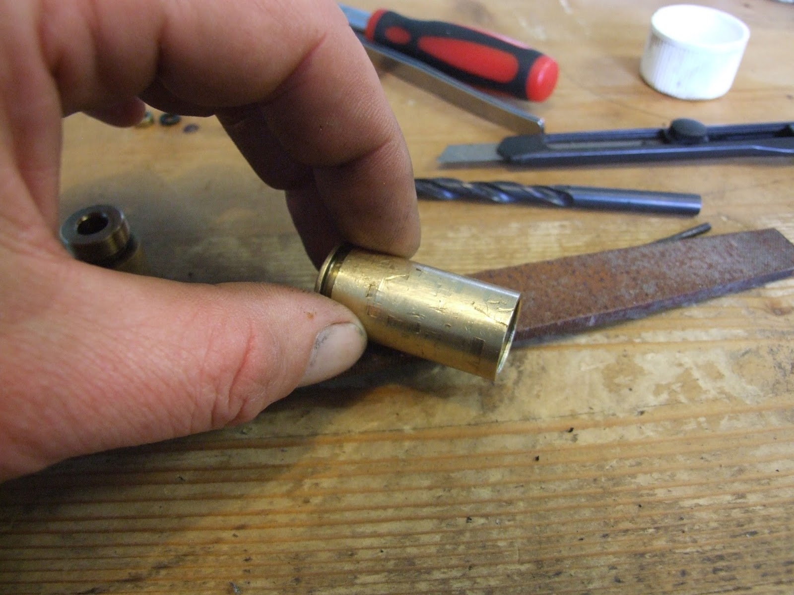
If the exhaust valve back guide is ever too tight a tool can be made up to fit the two small holes.

Then remove the spacer with the bumper inside it, the exhaust valve spring, and bumper plate - these should tip out into your hand. Using a piece of dowl from the front of the cylinder, push the valve out of the back, then remove the firing pin from the exhaust valve.

Valve with firing pin, bumper plate, spacer with bumper inside, and exhaust valve back guide.


The exhaust valve unit consists of the longer air chamber and the shorter exhaust valve guide. Unscrew them; you might have to use mole grips at first as they can be tight.

Remove the valve spring and inlet valve ball from the air chamber ...

Split the valve parts to get to the air inlet valve parts.

... and the exhaust brass valve stopper and exhaust valve seal from the exhaust valve guide.

valve guide, seal, and stopper.

inside the air chamber, the inlet valve packing is held in place by the inlet packing stopper. Unscrew the stopper using a wide fat blade, and the packing should fall out.

Inlet packing washer well and truly stuck in there.

(In this case, the packing was wedged in tight and I couldn't even prise it out, I had to very, very carefully mill it out using a mini drill and small drill bit so as not to damage the air chamber.)

Note inlet packing washer dust around the air chamber.

Milling into one side of the packing then the other, it eventually came out, spinning up the drill bit, leaving me with a grubby air chamber.


Needs a bloody good clean.

Clean the area where the packing washer sits in the air chamber with white spirits to remove any crap that might hinder a good seal.

Kitchen towel wrapped around a pick really shifts that crud.

Prise off the exhaust guide seal from the exhaust valve guide and the chamber seal off of the air chamber.
  
Oh so handy pick in action.

Then, with kitchen towel and white spirits, clean the air chamber (inside and out), the valve guide, packing stopper and valve stopper thoroughly.

Decanting a bit of white spirits into the lid keeps the rest of the bottle clean.

I lightly ran the outside of the air chamber and valve guide over a file to smooth out any scratches caused by the mole grips

Wet and dry or sandpaper will do also.

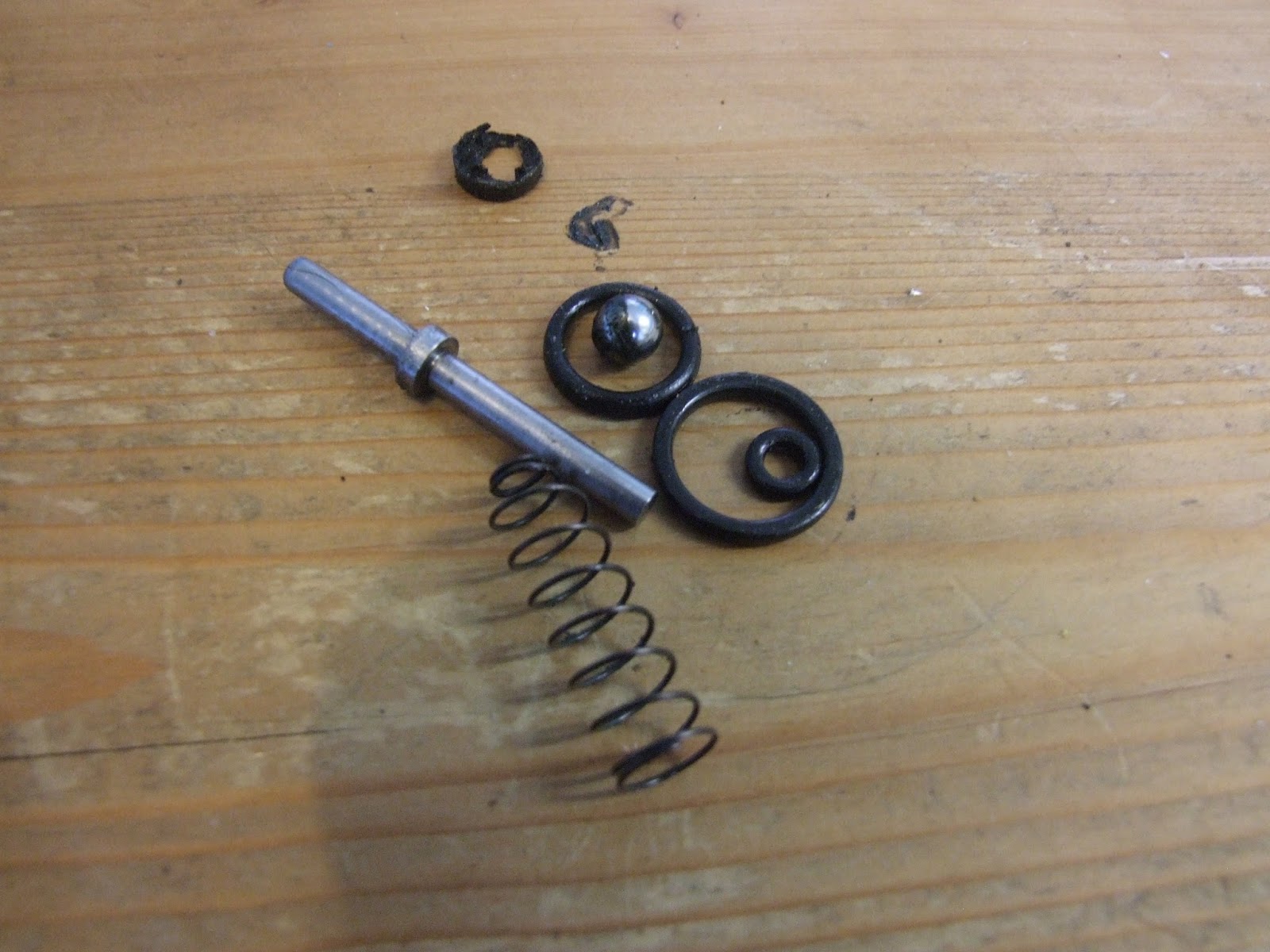
All the parts being replaced were put to one side; they consisted of the firing pin, the remains of the packing washer, inlet valve ball, exhaust valve spring, exhaust valve seal, exhaust guide seal and the chamber seal. 

Old worn parts, look at the state of that old packing washer.

Place the clean and replacement parts in order ready for rebuilding, along with a small blob of silicone grease for the O ring seals.


Lining up the parts for reassembly makes the whole proccess a lot easier.

Take the air chamber, insert the new packing washer and prod it into place.

That pick came in handy for prodding the packing washer into place.

Then the inlet packing stopper, guide it into place with your little finger.

Inlet packing stopper screwed in finger tight.

Then tighten it down using a wide flat blade.

Even tighter, though a chisel blade would be better than using the spacer.

Drop the inlet valve ball inside the inlet packing stopper to rest on the packing washer.

Inlet valve ball just drops in.

Place the valve spring on top of the inlet ball and put the air chamber to one side.

And so does the valve spring.


Take the new guide seal, thumb it over the screw thread of the valve guide and roll it into its recessed groove.

This is the smaller of the two large O rings.

Smear a dab of silicone grease over the new O ring seal.

The O ring spins around in it's groove easily.

Smear the new exhaust valve seal in silicone grease and pop it into the valve guide.

This is the smallest of the two small O rings.

On top of this goes the small brass valve seal stopper.

Seal stopper just pops in.

Align the air chamber with the exhaust valve guide so the valve spring sits on top of the valve seal stopper. Screw them together as tight as can be done by hand compressing the new valve guide seal.

Screw all the way un till there is no gap squashing the O ring for a good seal.

Thumb the new chamber seal into place, smear it with silicone grease and put the whole valve to one side.

The larger of the two big O rings is a tight fit

In order to get the best seal for the pump head and chamber seal, the inside of the cylinder needs a good clean. A few balls of kitchen towel soaked in white spirits pushed down the cylinder with a piece of dowel will loosen any crap ...

There was a lot of crap all in all.

... then ram a few dry balls of kitchen towel through until the inside of the cylinder is clean and shiny.

Ooooh, oh so shiny.

Pop the shorter end of the new firing pin into the valve guide end of the exhaust valve and align it with the back end of the cylinder, making sure the transfer port is aligned with the transfer port hole in the cylinder, and the same with the the stud hole.

Lined up correctly and ready for insertion.

Push it in until the stud hole appears in the bottom hole of the cylinder ...

That pick came in handy again for centering stud hole.

... it should be nice and tight with the new chamber seal fitted.

the longer end of the firing pin reaches the end of the cylinder.

Place the bumper plate over the firing pin and let it slide down to rest at the stop in the firing pin.
 
I must stop biting my nails.


Making sure the bumper is inside the spacer ...

This bumper only came out of the spacer if it was pushed out, some can be loose.

... insert it into the end of the cylinder to rest against the exhaust valve.

It really doesn't matter what order they are put in, as long as they're in the right order.

Place the exhaust valve sping inside the bumper to rest against the bumper plate, making sure the wider end of the spring is facing to the rear to rest against the exhaust valve back guide.

The valve spring must go in this way round.

Place the exhaust valve back guide on the spring, push into place and screw in by thumb.

Really needed that new exhaust valve spring, the old one barely pushed the back guide past the end of the cylinder.

Now the cylinder and valve can be returned into the breech, so with the old transfer port O ring seal out of the way, put a dab of silicone grease on the new O ring seal and press it in place around the transfer port.

The silicone grease helps the transfer port O ring stay in place.

When inserting the cylinder back into the breech, the cylinder is best pushed in along the bottom of the breech hole to stop the transfer port seal from moving out of place. The cylinder will stop short of the back of the breech hole, so pull the trigger and slide it back further until the stud holes in the breech and cylinder line up.

The hole in front of the stud screw is for a stud screw that pushes the spacer against the cylinder on most Innova's, not this one though.

Screw the stud screw back in lightly and slide the spacer into place so the forks of the spacer sit either side of the stud, then tighten the stud screw fully and screw the brass collar back onto the stud screw.

Only needs to be finger tight.

Fitting the pump rod, pump arm and linkage and front end sight unit is simply a reversal of the disassembly process.


I changed adaptors on my Deben Whisper silencer and fitted it to the action  so as not to piss off the neighbours, then it was off to the shed for a test of the muzzle velocity over the chronoscope.

The Deben Whisper comes with four adaptors, and I still can't use it on most of my air rifles.


Really must sort my shed out.

Two pumps gave me 257 FPS with 14.5 grain RWS Superdomes, which equates to 2.13 ft/lb.


Three pumps gave 392 FPS with Superdomes, which is 4.95 ft/lb.


Four pumps gave 463 FPS, which is 6.9 ft/lb.


Five pumps gave 501 FPS, which is 8.08 ft/lb.


Six pumps 550 FPS, which is 9.74 ft/lb


Soon after that the blow off valve cut in, but I was getting around 560 FPS by that time. This took the rifle up to just over 10 ft/lb.

Fitting new O ring seals to the loading bolt should up the muzzle velocity, given the state of all the other O ring seals they are most likely failing at the moment. Then if the muzzle velocity still needs to go up, I can adjust the blow off valve higher.

TTFN

All the best, Wing Commander Sir Nigel Tetlington-Smythe.